The term Custom Motor has many meanings. Let’s start with a definition of some terms to make this easier.
Custom Motor is typically a motor that has unique features and performance specific to the application and this set of requirements is not available when the project is started. Many custom motors move on to become standard motors which really depends on who has control over the design (the supplier or the customer). Some custom motors eventually become Industry Standard motors when multiple suppliers make the same configuration.
Industry Standard Motor is a motor with mechanical interface features and electrical configuration meeting NEMA, IEC, or a host of other Industry Standards or Codes. Several suppliers produce motors that meet this Industry Standard and the motors all mount into the same spot and operate with the same input power and control.
Standard Motor is a supplier specific term. There is nothing “Standard” about this motor, other than it is already designed and produced by that supplier and can be re-ordered. This should not be confused with the above, but it generally is a point of confusion.
Modified Standard Motor is another supplier term that identifies a motor that starts as a Standard and gets modified specific to customer requirements. This is usually a simple modification but can be as involved as a completely custom motor disguised as a modified standard.
COTS (Commercial Off The Shelf) Motor is another term for Standard Motor. It implies that the motor is available and may be ready to go when ordered, but this is generally not the case.
COTS is a term used by some government contractors that use this term to define something that has no export controls and was originally designed for another industry and is now used in a government funded project.

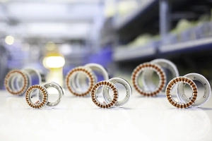
Example of a custom motor
Many motor designs originated for a specific application and started out as Custom Motors then later became a standard for the supplier. After multiple suppliers start to offer the same configuration and performance for the same application, Industry Standards were created.
Globally, Industrial and Commercial motors are dominated by AC Induction (Asynchronous) motor technology. Industry Standard frame sizes have long been established for several applications. A good example is AC pump motors which have an industry standard for defined mounting features and performance. All suppliers of pump motors must adhere to the Industry Standard to be compatible.
For certain applications that may be high volume, special purpose, or have a unique set of requirements, a non-standard form factor may be required. A good example is a washing machine which has an AC induction motor with a totally unique form factor and is highly integrated into the mechanical structure of the machine. It is considered customized solution or a Custom Motor. It is generally not sold to the general public or into other applications, except for repairs and service.
Unfortunately, there are not many Industry Standards for motors used in Factory Automation, Robotic systems, and Advanced Industrial systems. Each supplier has what they call a Standard Motor, (standard for them), but the form factor, mounting, and operation greatly varies from supplier to supplier. There have been some attempts at some industry standard definitions, (Like NEMA and IEC), but nothing has stuck globally.
MOTOR APPLICATION REQUIREMENTS
Each motor application has a set of requirements for form factor and electrical configuration. Early in the development of that application, one of three approaches were taken for motor selection;
- The company looked for a motor that was close to the size and configuration needed and used it
- The company requested a supplier to modify/develop a motor to exactly fit the requirement
- The company developed the motor internally or using a design service partner.
In option 1 or 2 above, the motor supplier now controls the design of the motor, the materials used in the motor, and the process for qualifying the motor. In a Medical Device, the design is well controlled and the process for production and materials is highly regulated. Selecting a “standard” motor or a “COTS motor” can lead to loss of design control and process control. The Semiconductor equipment market has the same issue, which is why it instituted CE or Copy Exact requirements.
Over time, motor users have continued to look for “Standard” motors at the start of projects because they were the easy fast solution. Easy and fast no longer drive key product and machine makers. Of course, there are many projects in the Factory Automation market that do not require design control and things like Copy Exact. If the motor comes with a different shaft, the coupling can be modified.
WHAT IS CUSTOMIZABLE IN A MOTOR?
(either a design from scratch or a modification to an existing motor)
1. Form factor
The diameter (if it is a rotary motor), the length, the shaft size, bearing size, overall outside dimensions, mounting dimensions, can all be changed to optimize for integration.
In the case of frameless motor kits, it is common to alter the sizes to match the mechanical integration needs, including a large through hole. Since there are no castings, bearings, and accessories, it is easy to modify the design specific to the need.
With traditional housed motors, it is more common to change the shaft and mounting face or the connector lead configuration but not touch the inside of the motor.
2. Weight
Optimizing (minimizing) weight is a typical process that usually follows magnetic design, electrical design and mechanical interface. Typical motors have iron, copper, and magnets, so the weight reduction really comes from design not from changing materials. For example, a high pole count motor may have smaller more concentrated flux paths leading to thinner iron cross-section and lower weight.
3. Torque output at a certain speed based on current and voltage input
Every motor has an internal electrical impedance, as well as some torque sensitivity relationship (Torque Constant, Kt). Speed is usually related to voltage applied and torque is related to current applied.
The application needs a specific torque at a specific speed, or it may have several operating conditions along a spectrum. Torque x Speed = Power (if units are correct).

4. Winding and Winding Contants
Resistance, Inductance, and Voltage Constant, (also known as Back EMF constant) are all measurable parameters and typically used for characterization and testing. A motor’s Torque Constant is related to its Voltage Constant. In certain motors, these two constants are equal when using the correct units. However, the impact of the motor driver and its internal technology really controls the Torque Constant.
Any motor can be wound internally to a specific Voltage Constant by altering the number of internal turns on each phase. Large motors with lots of room for copper will have a lower Resistance than small motors if the Voltage Constant is the same. Larger motors produce more torque because there is more moment arm, and because their resistance is lower so there is more thermal headroom.
Motor Constant is a calculation using the Torque Constant and the Resistance. It is a figure of merit used to indicate torque output with the thermal limits. In comparison between motors, Motor Constant (Km) is a good indicator of performance, efficiency and thermal constraints.
The Motor Constant and electrical time constant will not change if a motor is wound for a different Voltage Constant as long at the copper cross section stays the same.
5. Torque verses Angle characteristics
Every motor produces torque with angle as well as torque with current. The commutation process is aimed at optimizing to the maximum torque angle so torque is proportional to current and the control system is happy.
This is the most overlooked attribute in motors today. Because Voltage Constant = Torque Constant many motors (with units correct), the wave shape of the Back EMF curve should match the torque versus angle curve. This is generally not true because of things like cogging torque, and higher harmonics that are present under motor saturation.
6. Torque linearity
Torque linearity is mainly overlooked. Many motors have a saturation effect as current increases making torque output non-linear with current. Motors with iron that is highly saturated also have an issue with cogging torque. Slotless motors generally have very linear torque production with current, up to 3-5X the thermally rated limits.
7. Cogging Torque
Cogging torque will alter torque versus angle characteristics of an iron core motor. The frequency, amplitude, and phase of the cogging will distort the current producing torque. There are methods to minimize cogging. An axial skew in the motor laminations or the magnets can greatly reduce the cogging. An optimized pole count/slot count ration can also minimize the cogging torque effects. A motor without cogging torque is the best bet if the application requires smooth torque production, the system is operating in all quadrants of the torque speed, torque linearity is required, and precision positioning, torque control or speed control is required.
8. Inductance verses position characteristics
Motors with iron, typically have a change in inductance with position. The same mechanism that creates cogging torque also produces a change in inductance with angle. The great example of this is a stepping motor, where inductance can change more than 50% with motor angle. These motors make very good direct low speed servo motors, as long as cogging and inductance variations are not an issue mechanically or electrically.
Pole count sets the electromagnetic gear ratio within the motor, the number of electrical cycles versus the mechanical rotation angle. Lower pole count motors are typically better to run at faster mechanical speeds. Efficiency is greatly dependent on the electrical frequency. A high pole count motor will have its peak efficiency point at a lower mechanical rotation speed.
High pole count with high speed operating speed requires a high speed commutation loop (assuming it is a brushless electronically controlled/commutated motor).
Tooth count on the stator, (also called slot count), is normally selected based on the pole count and manufacturability concerns. High tooth counts generally require hand inserted coils distributed around the motor. Low tooth counts can allow for machine winding and lower labor content production. Segmented tooth stators require lower tooth count and can optimize copper fill by assembling after machine winding.
Slotless motors do not have stators with teeth (or slots). Instead, coils are placed around the magnet to make the electromagnetic phases of the motor. These motors are also can also be scaled in pole count and turn count. There is zero cogging torque in slotless motors.

The thermal resistance value includes conduction, convection and radiation effects. This is a first order term used as an indicator of the motors temperature rise versus the input power. Thermal resistance is measured in a certain environment while looking at the power input and temperature rise. The units are deg C/watt and a single thermal resistance is used from the motor winding to the ambient air. High end thermal models will have multiple thermal resistance value for every interface in the motor.
Thermal time constant is a measurement of how long it takes the motor to reach 63% of its final temperature. Once measured in a system configuration, it can be used to predict how a typical duty cycle will impact motor heating.
Changing these two attributes can be done by changing the construction of the motor. Usually, a requirement for insulating electrically conflicts with good thermal heat transfer. Selecting the correct insulation that meets standards but is also thermally conductive is tricky. Motors that are full encapsulated with a thermally conductive epoxy are generally better at evenly distributing the heat, reducing hot spots, and removing air from the motor. This reduces the overall thermal resistance and can increase the time constant.
If air can circulate over the motor windings (where most of the heat is generated), then a motor that is not encapsulated will achieve better results because the copper is directly cooled. So thermal environment takes some engineering and design to optimize.
11. Temperature Ratings
Based on 10 above, it is common for suppliers to perform a thermal testing with the motor under the most preferred thermal conditions. This is a good estimate of how the motor might perform but is typically misleading to customers because each project has a different set of thermal conditions and ambient temperature ranges. There really is not a consistent method for rating brushless motors and especially frameless motor kits. Read the notes carefully, some suppliers make it the customer’s responsibility to control the surface temperature of the motor mount.
None of the above is true for AC induction (Asynchronous) motors in Industry Standard frame sizes. These motors are tested for locked rotor and other conditions to handle the input power and not exceed the temperature ratings. Unfortunately, the brushless servo motor and frameless motor world has no standards to measurement.
12. Magnetic Induced Eddy Currents and Hysteresis
Most motors have eddy current losses. Changes in iron type and lamination structure, if the motor has iron in it, are typically done to reduce or increase eddy currents. Eddy currents act like damping in a control loop by producing a torque that is proportional to rotating speed and electrical frequency.
Hysteresis is also present in motors with iron. Changes in flux levels within the iron will create a friction (and heat). Lowering hysteresis usually involves change in the type of iron, or a reduction in the amount of iron.
13. Accessories like encoders, hall devices, temperature sensors, winding terminals, feed through connectors, etc.
These are all critical to interfacing with other systems and are typically altered to match each project. There are some compatibility requirements for mechanical size and electrical interface that must be considered. It is important to get a handle on the above 12 items before getting to the accessories section.
ARE CUSTOM MOTORS AFFORDABLE?
For lower volume, the decision is not so clear. Unique applications where the motor size and performance is the differentiator usually benefit from a custom motor solution. If the application has been solved already there may be at least one supplier that already makes something close. More traditional projects where a motor is just added to a machine without a need for small size or special performance typically drive the user to a more standard solution.
The cost of designing and producing motors has dropped considerably over the last 20 years. New production tools and sources are available for making low volume components, it is no longer a six-figure investment to tool up and make a motor. This is especially true for frameless motor kits where return on investment could be < 10 motors. Motor suppliers are more willing to modify their “standard” or create a custom motor if they can sell it into multiple applications. But be careful if you are making medical devices or something where you need design control. Finite Element Analysis tools are readily available and highly accurate allowing fast design turns while predicting complete performance, (if a motor designer is available and knows how to use them). The lead time to get a custom motor has generally come down. Due to global material shortages and supply chain and logistics issues, it is possible to get a custom motor in the same time it takes for the standard off-the-shelf motor. There are also suppliers that offer rapid prototyping. The biggest challenge is finding the right company/supplier to work with to creating the Custom Motor. There is a global resource constraint for design engineers. Motor designers are even more difficult to find. Select your team carefully, there are some very large industry leading motor suppliers with only a few motor designers. This may limit access to these people. There are small companies with several motor designers on staff.