Effective Motor Constant

Many motor specifications define how a brushless DC motor will perform, but only one allows a true motor to motor comparison of torque, associated power dissipation and temperature rise. That specification is the motor constant (Km). The units of the motor constant are Nm per square root of watts dissipated in the form of heat (these being I2*R losses, known as copper losses). This metric is a form of efficiency, but it only considers the copper losses. In a traditional, slot wound brushless DC (BLDC) motor, there are at least two other loses (see Figure 1 below), those being core losses, which include eddy current and hysteresis, and mechanical frictional losses, those being viscous friction, coulomb friction, and sometimes windage. A third form of loss that is not addressed here, is created by the pulse width modulated method of driving BLDC motors. This is an effect that is highly dependent on the inductance and frequency of the PWM rate and could also be considered under the right conditions. An Effective Motor Constant (Kme) is introduced to include core and copper motor losses (frictional and PWM losses ignored) and offers a more meaningful comparison of motor performance at speed.

Copper Losses and traditional Motor Constant
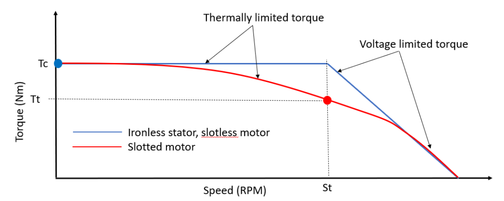
The theoretical shape of the torque speed curve for a BLDC motor is defined by applied voltage and the current (or thermal) limit of the motor (see horizontal blue line in Figure 2 below). The thermal limit is based on the maximum allowable winding temperature of the motor minus the ambient temperature. We use this change in temperature (ΔΤ) and the assumed thermal resistance (Rth) of the motor to solve for the allowable power that the motor can dissipate (Ρd). The allowable power dissipated is assumed to be the copper losses in the stator which are equivalent to the square of the phase to phase (DC) current times the hot phase-to-phase resistance of the winding.
(1a) ![]()
(1b) ![]()
Using these equations and the continuous stall torque rating of the motor, Motor Constant Km can be calculated.
(2) ![]()
This process has two shortcomings. First, it has ignored core and frictional losses. The power used in equation (2) is only from copper heating. The second issue is related in that the values used to calculate motor constant (Tc and Ic) are based on the motor producing torque at zero speed. The challenge here is that motors of different architectures behave differently with speed versus when holding under servo control, when considering core and eddy current losses. Unfortunately, this is a standard practice with almost every motor manufacture, so care must be taken when using the Motor Constant in selecting the right motor for high-speed applications. An alternative approach is to calculate an “Effective Motor Constant”.
Core Losses and Motor Architecture
A motor’s core losses are strongly dependent on both the motor architecture, whether the stator is slotted or slotless, and the operating speed of the rotor. Slotted motors of large diameters often have a high pole count, and as rotational speed increases, the surface speed of the magnets increases with the square, creating a rapidly changing flux field within the iron of the stator. The change of the flux direction caused by the rotating permanent magnetic field, as well as the changing electro-magnetic field within the stator, each contributes significantly to hysteresis and eddy current losses. Slotless motors, however, have no iron teeth, and as such have significantly less loss at higher rotational speeds. Traditional slotless motors still have an iron ring behind the copper for improved thermal conductivity and structural rigidity and with that iron comes some loss. Other slotless designs have no iron in the stator, and these architectures have almost zero core or eddy current losses.
True ironless stators, as mentioned above, when coupled with a two-sided rotor, have nearly zero eddy current and hysteresis loss. Motors with ironless stators are also highly efficient, nearing 95% or higher, and will have a flat torque speed shape versus a traditional slotted motor, which will roll off well before reaching the voltage limit (see Figure 2 above). It can be the case that a slotless motor with lower core losses can outperform a slotted motor that has a higher Km because operating speed favors the slotless motor’s higher efficiency. Slotless motors are often preferred because of their zero-cogging attribute, and in many cases, are better high-speed power converters due to very low core losses.
Core Losses and Effective Motor Constant
Core losses themselves are rarely listed in motor datasheets. In many cases, however, a torque-speed curve is available in the datasheet or upon request. Depending on the supplier, torque-speed curves may or may not include the speed-dependent losses. Figure 2 above shows a typical torque-speed curve with and without core losses (Red and Blue respectively).
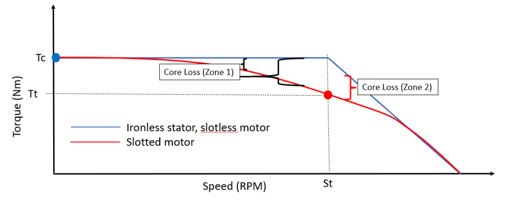
In Figure 3 above, the blue dot represents the continuous stall torque. When core and eddy current losses are not considered, and when also neglecting voltage loss from inductance, continuous torque remains constant until the voltage limit is reached. This value of torque is meaningful because it allows the calculation of only copper losses via the continuous stall torque and torque constant (see Equation 3). With the continuous phase to phase stall current (Icrsc) and the phase-to-phase resistance, copper losses are found using equation (4). It should also be noted that this amount of power, calculated at zero speed, is the total allowable dissipated power in the coil. Once the motor begins to rotate, other losses will come into play, but this value of allowable power will remain the same.
(3) ![]()
(4) ![]()
As mentioned in the previous section, copper losses calculated at zero speed are what sets the thermally limited part of the torque-speed curve when only copper losses are considered. Many motor companies will publish torque-speed curves with copper, core, and frictional losses (housed motors for example). An example torque-speed curve with copper and core losses is shown on the red trace of Figure 3. The red dot now represents the available torque considering the thermal impact of copper heating plus heating generated from eddy current and hysteresis. Note, in this case Ic and Icrsc are two different values. By finding the torque reduction between the continuous stall torque and any point along the red curve, up until speed St (the transition between the thermal and voltage limited part of the curve), and multiplying by the speed in radians per second, speed dependent core losses can be calculated.
(5) ![]()
For speeds above St, total power losses (Pt) must still be below Pcopper, to not overheat the motor, but now less current is flowing because the motor is voltage limited. In this case, we must first calculate copper losses (Equations 5 through 7). Pcore is then found subtracting copper loss that is voltage limited (PcopperVL) from Pcopper (Equation 9).
(6) ![]()
(7) ![]()
(8) ![]()
(9) ![]()
With known at any point along the torque-speed curve, total power loss (Pt)can be calculated using Equation 10.
(10) ![]()
The concept of an “Effective Motor Constant” is now available with Pt replacing the standard copper losses (Pcopper). Note that Effective Motor Constant is now a function of speed. Using Tt from Figure (2), Equation 7 below defines an Effective Motor Constant (Kme).
(11) ![]()
Impact of Effective Motor Constant
The traditional Motor Constant does not consider thermal effects above zero speed. Sizing a motor based on early requirements, such as required torque and allowable temperature rise, could lead to an overheating motor at speed.
Motor selection is done many ways. Some start with a torque, outer diameter, length, and mass, while others go straight to a torque-speed curve, prioritizing performance over the physical specifications. For those going with option 1, speed and temperature are ignored. Motor torque almost always* is nearly flat at low speeds, and once the voltage limit is reached, it decreases until reaching the No-Load Speed. * denotes exceptions that take advantage of “windage”, a cooling effect of air flowing across the face of the stator coils. When this happens, the torque-speed curve can increase until reaching the voltage limit, as the thermal resistance is decreasing with speed. This torque-speed dependency makes selecting a motor based on only continuous torque required a risky endeavor. Stated continuous torque is generally listed with assumptions on operating temperature, both ambient and maximum winding temperature. So, although a torque might be met via the listed continuous stall torque, or even via the torque-speed curve, there is an underlying statement about temperature, that may or may not work for the application. This leads to option 2, looking only at the torque-speed curve. As previously mentioned, this process does take speed into account, but still lacks consideration of application specific operating temperature while at speed.
Without getting into details about motor housings and heat path, the best way to compare two motor options is to consider the Motor Constant Km. A higher Km motor will either run cooler for the same continuous torque or provide more torque for the same temperature rise. It is that simple. What is not simple however, is understanding how this metric works at speeds other than zero RPM.
This is where Effective Motor Constant brings value. The process shown above to calculate the Effective Motor Constant at a speed will allow the user to know which motor will run cooler, or which motor will provide more torque for the same temperature.
EXAMPLE:
This is a medical device application. Due to touch temperature limitation, winding temperature is a limiting factor in performance.
Motor selection begins with calculation of required motor constant to keep winding under 80 ºC .
Required torque is 0.75 Nm at 1100 RPM.
Two motors identified. One is a slotless motor. The second is a traditional slotted motor. Both are similar size in outer diameter and stator length.
Spec sheet says both have similar thermal resistance (which makes sense since both are similar in diameter and length): Rth = 1ºC/W.
Ambient Temperature: 25ºC
Allowable Dissipated Power (from Eq 1a):
![]()
From Eq. 2:
![]()
This is the Motor Constant needed to meet the required torque while not exceeding a winding temperature of 80 ºC.
Now let’s look at two possible motors. Per the datasheet:
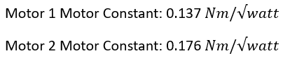
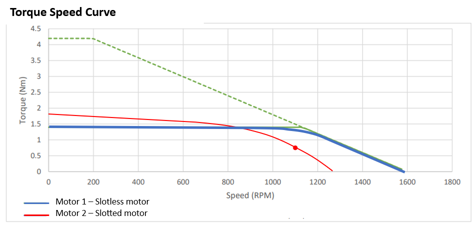
At this point, per the datasheet, it appears both motors 1 & 2 exceed the required Motor Constant of 0.101 Nm/√watt. But, motor 2’s torque-speed curve is an indicator that we have not considered the speed dependent losses, and what impact that will have on temperature rise while meeting the required torque.
Let’s now calculate the Effective Km with the method defined above.
Motor 1:
Kme is the same as traditional Km as there are minimal speed dependent losses at 1100 RPM.
Motor 2:
Torque Loss at 1100 RPM = 1.8 – 0.75 = 1.05 Nm (this is Tt )
Core Loss (Pcore) = 1.05 * 1100 * 2 * pi/60 = 120.9 W
Since the speed is less than the transition speed, we can calculate the total power loss using Eq. 10 from above.
Pt = Pcopper + Pcore = 105 + 120.9 = 225.9 W
![]()
Effective Motor Constant shows that although the motor can achieve the required torque of 0.75 Nm, the winding will rise above the required 80ºC at 1100 RPM. This temperature effect is not readily known by looking at only a torque speed curve (if one is available), or by selecting a motor based on the traditional Motor Constant. The impact is only realized when an Effective Motor Constant (Kme) is calculated.