Selecting motors for robots with tight thermal constraints
Ok, you are selecting a motor and you click around. There are plenty of motors with 1 NM of torque at 1000 rpm you require. Pick the one that is available and has the best combination of size, weight, features, and price. Wait, is it that simple?
Well… only if the motor you are selecting complies with a rating system driven by a certified body, for example, a NEMA Frame AC Motor with a NEMA Nameplate. These motors have been tested to their nameplate and all manufacturers meet the same test conditions. If there is no industry rating or international rating system, then all bets are off.
Unfortunately, there are no widely accepted rating standards for newer advanced motor technologies. Most datasheets for servo motors, brushless DC motors, permanent magnet AC motors, brushless AC motors, torque motors, (… the names go on forever…), need substantial review. For years, manufacturers in this space have used their own internal methods for measuring, rating, and publishing performance. The 1 NM motor may only produce 1 NM when it is connected to a heat sink and placed in a room at 25 C ambient. On top of that, it may assume the motor’s internal temperature can rise to 150 C making the housing over 130 C, probably too hot for most collaborative working environments, including robotic assisted surgery device equipment.
Another limitation of manufacturers datasheet information is that thermal conditions and testing are typically hidden or at minimum in the foot notes. Choose your motor carefully.
Motor Internal Ratings
Internal temperature is a key requirement when a motor is designed. The temperature rating impacts selection of the magnet, the wire, the insulation system, bearings and overall mechanical design. This one parameter touches just above everything in the motor. Motor manufacturers routinely select a maximum temperature and work back from there. Underwriters Laboratories (UL) and other safety organizations have historically rated electrical materials based on temperature. A UL Class B rating is 130C, for example. If Class B is selected for operation, then electrical materials should be rated at above 130 degree C.
Most magnets have a reversable temperature coefficient between 1 and 10%/100 deg C. This means a magnet rated at 25 C may lose 10% of its strength at 125 C then return to full strength after cooling. There is also an irreversible temperature coefficient. For example, if the magnet above reaches 150 C (above the reversable temperature limit) then it may permanently lose 25 % of its value after cooling. If the magnet is internal to other materials that get hot it may see hot motor temperatures due to its environment. Some magnets are rotating on a shaft separated from the coil and can see much lower temperatures.
Internal temperature and external temperature are connected by the thermal resistance of all barriers between the heat source and the outside of the housing. Most motors that are fully assembled, (as opposed to frameless), have multiple internal components that impact how heat flows from the source to the outside. It is routine for manufacturers to mount the motor to a heat sink that emulates a possible application. Small motors tend to benefit greatly from this conduction into the mount, large motors have more surface area for convection and depend less on conduction to the mount.
Frameless motors are very popular today for advanced industrial and robotic applications. Designers highly integrate these motors in mechanical systems. This poses a more complex problem of designing for thermal requirements since the motor does not have a mounting surface and depends on the customer mechanical parts to be the housing.
Beware of motors that have internal electronic components. Most combination motors will carry a derating to minimize the impact on electronic components. Many of which can only handle 80 C. Power loss is generally related to copper heating, which is a function of the current squared. If a motor has a thermal resistance of 1 deg C/watt, going from 130 C down to 80 C would reduce allowable heating by 50 watts.
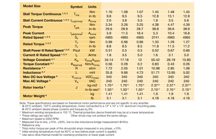
Below is a typical motor datasheet parameter table. The only measurable items are Voltage Constant, Resistance, Inductance, and Weight. The rest of the items are either calculations or inputs to the motor.
The notes below the table really identify the conditions use. It assumes that the motor is in 25 C ambient and asks for a derating if used in 40 C ambient. The maximum winding temperature is 155 C indicating class F insulation system. Torque output is based on these thermal conditions and a condition that motor is mounted to a 10 inch X 10 inch X .25 inch Aluminum plate. All measured parameters are +/- 10% and some are higher.
If you are going to use this motor in a medical device, like a robotic assisted surgery system, it will be in the operating room so 25 C is probably reasonable. The robot will not have a large Aluminum plate. It has patient surface temperature limits in the low 40 C range, so the available temperature rise over ambient, (dictating the power that can be dissipated), is only 15 C.
Comparing the use conditions to the motor specification you will get the following;
- The motor ratings could vary 20%. To be safe derate the output to 90% to cover the low end of the specification.
- The motor datasheet assumes heat rise of 155C-24C = 130 C above ambient. The application can only handle a 15 C rise on the surface of the robot.
- Assuming the internal motor temperature of the motor can be 50% higher than patient surface temperature (this is very generous, and needs to be tested), we can stretch the internal motor temperature to 30 C rise above ambient.
- 30C/130C = 23% of the datasheet heat rise. This might yield 46% of the rated torque but that must be derated to 42% of the datasheet value to account for parameter variation.
Datasheet information should be treated as a reference in most applications. Medical devices that have patient contact really have a different set of rules compared to general purpose factory machinery.
So, how do I select a motor?
Answer 1: A thermal model/simulation or empirical testing is required first.
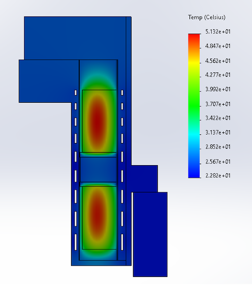
Since thermal limits are the driving factor in most designs, a plan must be devised to model/simulate or measure system thermal performance. Tools like finite element analysis (FEA) and thermal flow analysis are available as an add-on to most CAD packages. There are more complex thermal modeling tools also available that combine CFD and lumped parameter thermal models. Below is a temperature analysis for a mechanical structure. The sources can be assumed to be motors and show a hot temperature of 51.2 degrees. The outside of the housing is 22.8 degrees and the ambient temperature was 20 degrees.
Figure 1 FEA Thermal Analysis Results
The above analysis includes a special active cooling system within the mechanical assembly to mitigate heating on the surface. The simulations usually provide thermal resistance values that can be used for later predictions without having to re-solve using FEA.
Empirical testing is another option for a 1st pass analysis. Use an existing assembly or mock-up of the system and empirically make thermal measurements. This can be done using a heating element in place of the motor. Applying a known input power will allow the temperature to be measured at each area of concern. With this data thermal resistance can be calculated.
Thermal resistance measured in degree C/watt is the most useful tool estimating temperature. In a true thermal model, each interface that heat travels through has a thermal resistance. Simple lumped parameter models that emulate electrical circuit modeling are generally used. It is also common to use only one or two thermal resistance values for gross estimation.
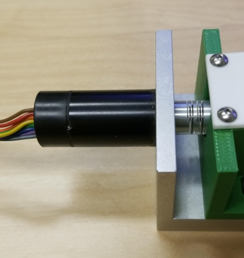
Mounting a complete motor onto a frame is a good example here. If the motor itself can be used as the heating element. Power is applied and temperatures are recorded. A certain amount of heat will transfer into the air and some will transfer into the mount.
Figure 2 Motor Mounting
Empirical testing for Thermal Resistance is straightforward. Instrument the motor with thermocouples on the housing and mounting bracket. Five datapoints are critical.
- Motor internal winding temperature
- Motor housing temperature
- Mount temperature
- Ambient air temperature
- Internal ambient temperature if the motor is enclosed in another assembly
Apply power to the motor winding using a power supply. Preferably, a power supply that offers current limiting or voltage limiting functions, (most lab power supplies can do this). It is best to set the power supply in current limiting mode and apply current below the limit of the motor (based on datasheet value). While applying current to the motor monitor the voltage required to keep the current flowing.
Because the motor is mainly a resistor (when not rotating), voltage will increase with temperature due to the resistivity of copper, (.0039 ohm/deg C rise). Simply applying power and measuring the initial voltage and the final voltage (at steady state) will allow you to calculate the change in temperature.
Installing a thermocouple, or using a hand held IR temperature gun, will allow you to measure the housing temperature and mount temperature at steady state. After power is applied and the system reaches steady state (final temperatures), the change in temperature of each location can be calculated.
Example:
- 5 watts of power is applied to the above motor system in a room that is 25 C.
- After 25 minutes the input power is now 7 watts because voltage has increased 40% in order to keep the current constant.
- Final winding temperature is 125 C based on the 40% change in voltage.
- Internal motor temperature rise is 125-25 = 100 C.
- Motor housing temperature is 100 C and Mount temperature is 50 C. This assumes you average temperature using an IR thermal gun.
- Thermal Resistance (motor winding to Air) = 100/7 = 14.28 deg C/watt
- Thermal Resistance (motor winding to motor housing) = 25/7 = 3.57 deg C/watt
- Thermal Resistance (motor housing to mount) = 50/7 = 7.14 deg C/watt
- Thermal Resistance (Mount to Air) = 25/7 = 3.57 deg C/watt
You now have your basic thermal model. You can look at any thermal resistance value in the chain using this simple method. Radiation effects and any changes to due air moving over the system have not been considered. This first order approximation does not cover hot spots and other unique conditions that may be present.
If you want your device external temperature to be limited to an absolute value of 42 C in a 25 C ambient, then you must reduce the input power to 68% of the test value above, or 4.76 watts.
Another important result from testing shows that the motor winding is at 125 C, which is at the limit of the motor manufacturers rating for this motor. Motor ratings generally assume the motor is mounted to some aluminum. Be careful if you make 3D parts out of non-metal materials you are effectively insulating the motor, and its rating will be reduced.
Motors produce heat in three ways, copper losses, core losses and mechanical rotational losses. Copper losses are most widely known and relate to the testing we did above. Core losses are a function of eddy currents and hysteresis losses as the motor’s magnetic fields are changing typically with rotation speed. Mechanical rotational losses are from bearings which can really impact motor temperature at high speed depending on bearing type and grease. It is important when using your thermal model to identify all of the watts of heating that will be present.
Answer 2: Go for the highest Km motor available in the size that also meets other constraints like smoothness, then build your system and measure it thermally making adjustments for performance to reduce heating if it is a problem.
Km = Kt/SQRT(R) where Kt is the torque constant and R is the resistance. It is a figure of merit for torque output for the amount of heat generated. Size and motor design come into play here. Going for the largest motor you can fit is sometimes the best approach as long as weight is not a factor.
It is best to follow the path of Answer 1 then pick the motor based on Answer 2. If you know the thermal resistance and the thermal limits, then Km can be used to select a motor.
Summary
The bottom line is that you will need to model or measure the assembly around the motor before you can really select a motor. Unfortunately, most users focus on the torque requirement or a mechanical fit requirement, then hope the thermals work out. Some motors are used in torque mode, others are used to produce some power output (torque at a certain speed). Efficiency only is relevant when motors are moving, so avoid selecting a motor based on an efficiency number because it may be at a speed you are not operating at.
If you are considering a more complex assembly with frameless motors and highly integrated encoders and electronics, you will need more comprehensive thermal models at the starting point for design. It is possible to have multiple heat sources in different locations if the FEA modelling is used.


